A poor scan of a socket has the same value as a poor cast—or lack thereof. A little skill, experience, and some magic might make up for some shortcomings in your scan. But good enough is never a great strategy, especially when the few minutes that it will take to rescan can save you the cost of a new socket and hours of fitting.

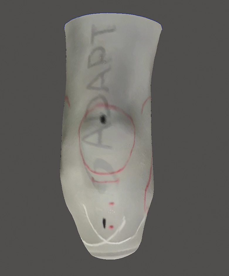
To start a high-quality scan, be sure to capture the complete distal end of the residual limb and leave no holes in your image. Capturing the distal cup in your scan will provide you with the correct placement for your lock dummy and save your patient the discomfort and headache of chasing that wonderful click of engagement. I like to pull a nylon or stocking over the liner so I can draw my landmarks, modifications, trim lines, and vertical alignment on the sock. This will provide an excellent reference when you are using a scanner with full-color capabilities like Comb or SnugFit. If possible, pull the nylon off center so the seam of the nylon does not cross the distal cup. It may seem to be an insignificant wrinkle that surely you can easily smooth out, but you should be as wary of waving your smoothing tool across your model as you would be of using your Surform file on a cast. Details can easily be distorted, and landmarks disappear. In the scan image, you can see the seam from the nylon off center, vertical alignment marks, and landmarks (Figure 1).
Next, I want to talk about alignment. While it may seem obvious, I want to emphasize that pin alignment and prosthetic alignment are not the same thing. The puck type of locks with the four-hole attachment built into the lock are great. They are lightweight, convenient, cost-effective, and ubiquitous. There is a reason that lock manufacturers also produce shift plates and pyramids. The pin position does not always line up vertically where we need it. If we do not reconcile that fact with our socket, we can cause some user discomfort or end up replacing liners prematurely.
I have found it helpful to lay a vertical plane on my model to note the difference between pin and vertical alignment. This can help to provide a visual guide during the modification process. Unlike a plaster model where you are forced to view your model in the position of your pipe or mandrel, you can also use a vertical plane to determine and set your bench alignment before fitting. By measuring my planes, I can see the model in the example needs to be shifted about 9mm and is abducted 5 degrees (Figure 2).

There is another alignment consideration if you are going to import your image into rectification software that does not use the mesh. The image needs to be imported in the pin alignment because a centerline will need to be set at the most distal point on the model, and a series of cross-sectional lines will slice the model up like an MRI. To illustrate this, I imported the same shape, one in the pin alignment (Figure 3) and another in the vertical alignment (Figure 4). In both images I placed a line at the lower edge of the liner distal cup, the point that I would flatten to set my lock dummy on for fabrication. The image imported in the vertical alignment looks relatively distortion free but would have me placing the lock far too medial, and the alignment would likely force the pin at the wrong angle.


In the anatomical alignment image (Figure 5), I placed a horizontal plane across the patellar tendon mark on my model. With the model set in the pin alignment you can see the position of the anatomy is independent of the alignment on which the model was imported. Also, the marks for the medial and lateral trimline are not equal, which is yet another consideration to keep in mind while you are applying your modifications to the surface of the model.
Fabricating a socket for use with a pin system is a relatively simple formula: Flatten the distal end equal to the amount of liner that will sit inside of the lock. Hopefully, when the socket is made and fitted, the patient will slide in with ease, engage the lock, and compliment you on a job well done.
Remember though, hope is never a good strategy. Take a good scan. Understand your digital process and enjoy great, worry-free fittings.
Chris Cummings has worked in O&P for 32 years. He is currently directing central fabrication operations and new product development at BioSculptor Corporation. He can be contacted at [email protected].