
Modern lower-limb prosthetic components can be broadly characterized by their power requirements. Mechanically passive devices that require no external power are the most basic of these types of components. In addition, the profession now has access to a number of intelligent passive devices that draw minimal battery power to support microprocessors that manipulate their dampening characteristics in real time, providing optimum ankle and knee resistance according to such variables as speed, slope, terrain, and activity. Finally, there is a third, more recently developed category of components that draw from external power sources to generate positive torques as needed during gait and other activities. In the first article on this topic, the two components with the most robust descriptions in the literature, iWalk’s BiOM foot and the Vanderbilt Knee (originally developed at Vanderbilt University, Nashville, Tennessee, it is not yet commercially available but is licensed to Freedom Innovations, Irvine, California, for eventual release), were reviewed (“The Dawn of Powered Lower-Limb Prostheses,”The O&P EDGE, March 2013).
However, in addition to these more well-known design approaches, there are several other developing components that can be placed within this third category of active powered prostheses. Drawing power from pneumatic bladders, springs, and battery-driven motors, these ankle and knee components also attempt to restore net positive joint motions at the lower limb. The purpose of this second article is to introduce these lesser-known powered components.
Pleated Pneumatic Artificial Muscles
The first component of interest is a foot and ankle unit being developed in Belgium that draws its power from pneumatic actuators, termed “pleated pneumatic artificial muscles” or PPAMs.1-2 The arguments in favor of a pneumatically driven prosthesis include the following:1
- Relatively lightweight design.
- Capable of generating high force.
- Inherent compliance.
- Graceful degradation and failure.
- Does not require a complex gearing structure.
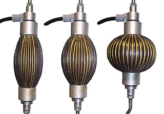 Different contraction levels of PPMAs (example is the Air Muscle from Shadow Robot, London, England).
The PPAMs currently described in these efforts were still tethered to an external energy source, with the objective of autonomous use beyond the scope of the early prototype research. The developers of the PPAMs also identified a number of target design specifications. These included an output torque of 1.7 Nm/kg, an ankle range of motion (ROM) of about 30 degrees, and the ability to adjust ankle stiffness according to walking speed.1
The actuation method of PPAMs can be described as follows: When the enclosed membrane of a PPAM is inflated, it bulges out circumferentially, creating a contractile force along its long axis. By contrast, deflating the membrane allows the unit to recover into relative axial elongation. Because PPAMs are only capable of contractile, or pulling, forces they must be coupled antagonistically to produce the bidirectional motion of the ankle joint. In the Belgian prototype, the prosthesis included a low-profile prosthetic foot attached to a custom-made, two-dimensional ankle joint followed by an axial pylon.
A single anterior PPAM was used to simulate the actions of the dorsiflexors. Because of the higher energy demands of the plantarflexors, two parallel PPAMs were used posteriorly to generate the required torque.1-2
The relative pneumatic pressures within the PPAMs were regulated according to the timing of the gait cycle to provide appropriate energy absorption or torque output as required. For example, after heel contact, the advancement of the ankle into a predetermined dorsiflexion angle signals a need for torque generation in the two posterior PPAMs. This occurs as they are inflated, which increases their internal pressures and generates contractile forces. Simultaneously, the pressure in the anterior PPAM is decreased to allow it to elongate antagonistically as the foot plantarflexes through push-off. After toe-off, an increasing pressure in the anterior PPAM, coupled with decreased pressure in the two posterior PPAMs, creates a restorative swing-phase dorsiflexion.2
The promise of this approach within the published literature is currently limited to the results of a single subject in a controlled laboratory environment, tethered to an external pressure source.1-2 However, the proof-of-concept prototype demonstrated an ability to mimic normal ankle ROM and push-off torque across both self-selected and as fast-as-possible walking speeds. The case subject described the prosthesis as safe and comfortable and reported the extra pushoff torque to be beneficial.2
The SPARKy Approach
A separate strategy using electric actuators has been developed in a collaborative effort by researchers from the United States Military Academy at West Point, New York, and Arizona State University, Mesa.3-4 In introducing the concept behind their approach, the authors addressed what they described as the inadequate power density (power-to-weight ratio) and energy density (energy-to-weight ratio) in traditional motor actuation schemes.3 In response, their model, the SPARKy, or Spring Ankle with Regenerative Kinetics, utilizes a “robotic tendon actuator” that couples an electric motor with paired helical springs.4-5 The springs, positioned posterior to the ankle joint, absorb mechanical energy throughout stance as the advancing tibia pulls them into relative deflection. In addition, a lightweight, relatively low-energy motor is positioned at the proximal end of the springs. The motor is used to further extend the springs to achieve the desired potential energy. At push-off, the energy-efficient springs release their stored energy to generate the required ankle moment.3-4 Because the majority of the system’s power is derived from the conservative mechanical energy of the cyclically elongated and released springs, the power requirements of the motor are low. This increases both the power and energy densities of the system.3-4
As with the Belgian PPAMs, the promise of this first generation SPARKy was initially limited to the observations upon a single transtibial case subject walking on a treadmill. During those observations, the authors were able to demonstrate a 4.5 power amplification by coupling the electric actuator motor with the mechanical spring. Specifically, as the subject walked at a steady state speed of 1.3 meters per second, a push-off force of 270 watts was generated. Of this value, 210 watts were provided by the springs with the motor only providing the remaining 60 watts.3 The pairing of the springs with the motor-driven actuator ultimately created a system that was 81-percent efficient in its power consumption, with an average electrical power of 43 watts into the motor, which yielded an average mechanical power to the user of 35 watts.3 In addition, the SPARKy was seen to maintain ankle kinematics consistent with able-bodied gait and provide 100 percent of the power required for push-off.3
The same research team later produced a derivative foot designed for transtibial running using many of the same concepts.5 In doing so, they observed that the transition from walking to running triples the energy requirements during the gait cycle. Further, the stride frequency nearly doubles, meaning that a running-specific prosthesis would have a power requirement six-times higher than that of a walking prosthesis.5 This led to a redesign of the SPARKy concept that included structural modifications to accommodate the increased dynamic loads experienced during running and increased actuator power by dedicating a separate motor-driven actuator to each of the posterior spring elements.5 These refinements allowed a case subject to successfully run on a treadmill at gait speeds up to eight miles per hour and led the research team to recognize that further increases in actuator power were still needed to fully meet the needs of transtibial running.5
The Power Knee
In contrast to the other developmental design concepts presented in this review article, the Össur POWER KNEE™ has been commercially available for several years. However, there is no mention of its design and development in the academic literature, preventing a review of its construction or control schemes. However, it has been the subject of two recent third-party clinical trials.6-7
In the first of these, Highsmith et al. evaluated the ground reaction forces (GRF) and the hip and knee moments observed in both able-bodied controls and subjects with transfemoral amputations during sit-to-stand and stand-to-sit transfers.6 Asymmetry values were determined for all subjects by comparing these variables as observed on both lower limbs, dominant versus nondominant sides among controls, and prosthetic versus sound side among persons with amputations.
Among controls, these values were consistently less than 7 percent, suggesting that the loads experienced during transfers were generally borne equally by both limbs. By contrast, the asymmetry values among subjects with amputations were always quite high, with subjects consistently demonstrating an increased reliance on their sound-side limb. More specifically, the subjects all performed the tasks using three different prosthetic knees. These included Össur’s mechanical Mauch® SNS knee, the variable dampening Ottobock C-Leg, and the externally powered POWER KNEE. Among the subjects, sit-to-stand GRF asymmetry was lowest with the POWER KNEE (mean = 53 percent) relative to mechanical (mean = 69 percent) and variable-dampening (mean = 65 percent) knees. Similar trends were observed during stand-to-sit transfers, with GRF asymmetry values for the POWER KNEE (mean = 32 percent) being less than those observed with both variable-dampening (mean = 53 percent) and mechanical (mean = 60 percent) knees, but higher than those observed in controls (mean = 6 percent).6 Comparable trends were observed for both hip and knee moments in both sit-to-stand and stand-to-sit transfers.6 Taken collaboratively, the data suggest that the subjects were somewhat less reliant upon their sound limbs during these transfer activities when using the powered prosthesis compared to the mechanical or variable-dampening knees. However, the asymmetry values were still much higher than those observed in controls.6
A separate clinical trial evaluated the effect of the POWER KNEE on the biomechanics of ramp ascent and descent and step-over-step stair ascent and descent.7 This latter distinction is important as most transfemoral prosthesis users will employ a step-to stair-ascent strategy with a mechanical or variable-dampening knee prosthesis, advancing their sound limb to the next higher step and then bringing their prosthesis up to the same step. The average peak knee power generated by the sound limb during step-over-step stair ascent while wearing a variable-dampening prosthetic knee was more than four times greater than that observed while wearing the POWER KNEE as the subjects would thrust themselves up the stairs with their sound-side lower limb. With respect to the affected limb, the peak knee power generated by the POWER KNEE was four-times greater than that observed with the variable-dampening knee.7 While the powered prosthesis appeared to provide clear functional benefits during stair ascent, it did not outperform the variable-dampening knee in the other tested tasks of ramp negotiation and stair descent where the use of the nonpowered knee produced greater speed and symmetry.7
Agonist-Antagonist Active Knee Prosthesis
Observing the high energy requirements of the POWER KNEE, a separate design strategy for a powered knee prosthesis has been proposed that seeks to leverage the passive dynamics of the knee during gait while mimicking the elastic energy storage and return of the anatomic knee.8-9 This design returns us to the earlier concept of series elastic actuators (SEAs) in which the elastic energy output of a mechanical spring is modulated by an inline motor that regulates its compression during gait events. An additional defining feature of this agonist-antagonist active knee prosthesis (AAAKP) is the parallel positioning of two SEAs in an agonist-antagonist arrangement, with one acting as a knee extensor spring and the other acting as a knee flexor spring.8
A basic description of the roles of the flexion and extension SEAs during ambulation is as follows. Beginning at heel strike, the motor of the extension SEA is locked, engaging the extension spring such that it absorbs and stores energy during stance flexion. Once the knee reaches maximum flexion, the motor of the flexion SEA is locked. As the knee begins to extend, the energy stored by the extension spring is progressively transferred to the flexion spring. It is stored in this spring until preswing when it is released to propel the knee into rapid flexion in preparation for swing.8
As the knee transitions from stance phase to swing phase, the targeted behavior of the knee changes from energy storage and return to motion dampening. During initial swing, once the knee flexes past 60 degrees, the extension spring engages, dampening excessive knee flexion. Similarly, during terminal swing, when the knee extends to within 15 degrees of flexion, the flexion spring engages to dampen the extension of the knee for a smoother deceleration.8
Because of the energetically conservative design of the antagonistic SEAs, the electrical power requirements of the AAAKP are low, measured at only eight watts. This is a marked reduction in power consumption compared to the nonconservative, direct-driven designs that consume over 25 watts.8 The reduced power requirements permit a battery mass for the AAAKP more than five times smaller than that required by the POWER KNEE.8 However, the motorized design of the knee is such that knee-joint torques can be increased through the action of the SEAs to respond to more energy-expensive tasks such as stair and ramp ascent.
Thus, the design addresses both the energetically conservative task of level ground walking as well as nonconservative, high-power movements.
Published observations of the AAAKP in clinical applications are limited to a single case study in which the subject ambulated in both the AAAKP and a variable-dampening, microprocessor-controlled knee with no changes to his socket or prosthetic foot. While using the AAAKP, the subject experienced a 17-percent increase in his self-selected walking speed and a 7-percent decrease in his metabolic costs, despite a modest increase of .8kg in the weight of the prosthesis.9
Summary
In summary, there are a number of different design strategies that are currently being explored in various attempts to provide powered prosthetic movements. These include manipulating pneumatic forces, direct-drive motors, and SEAs in which comparatively smaller motors are used to amplify the forces of mechanical spring elements. With all of these prototype designs demonstrating some level of promise, practitioners can look forward to further design refinements and larger scale clinical trials as the profession draws closer to the goal of powered lower-limb prosthetic movement.
Phil Stevens, MEd, CPO, FAAOP, is in clinical practice with Hanger Clinic, Salt Lake City, Utah. He can be reached at philmstevens@hotmail.com
References
- Versluys, R., A. Desomer, G. Lenaerts, and M. Van Damme. A pneumatically powered below-knee prosthesis: Design specifications and first experiments with an amputee. Paper presented at BioRob 2008. 2nd IEEE RAS & EMBS International Conference. Biomedical Robotics and Biomechatronics 372-7.
- Versluys, R., G. Lenaerts, M. Van Damme, I. Jonkers, A. Desomer, B. Vanderborght, et al. 2009. Successful preliminary walking experiments on a transtibial amputee fitted with a powered prosthesis. Prosthetics and Orthotics International 33(4):368-77.
- Hitt, J., T. Sugar, M. Holgate, R. Bellman, and K. Hollander. 2009. Robotic transtibial prosthesis with biomechanical energy regeneration. Industrial Robot: An International Journal 36(5):441-7.
- Hitt, J., T. Sugar, M. Holgate, and R. Bellman. 2010. An active foot-ankle prosthesis with biomechanical energy regeneration. Journal of Medical Devices 4(1):011003.1-9.
- Hitt, J., J. Merlo, J. Johnston, M. Holgate, A. Boehler, K. Hollander, T. Sugar. 2010. Bionic running for unilateral transtibial military amputees. Paper presented at 27th Army Science Conference. Accessed at: oai.dtic.mil/oai/oai?verb=getRecord&metadataPrefix=html&identifier=ADA532485.
- Highsmith, M. J., J. T. Kahle, S. L. Carey, D. J. Lura, R. V. Dubey, K. R Csavina, et al. 2011. Kinetic asymmetry in transfemoral amputees while performing sit to stand and stand to sit movements. Gait & Posture 34(1):86-91.
- Wolf, E.J., V. Q. Everding, A. L. Linberg, B. L. Schnall, J. M. Czerniecki, and J. M. Gambel. 2012. Assessment of transfemoral amputees using C-Leg and POWER KNEE for ascending and descending inclines and steps. Journal of Rehabilitation Research & Development 49(6):831-42.
- Martinez-Villalpando, E. C., and H. Herr. 2009. Agonist-antagonist active knee prosthesis: A preliminary study in level ground walking. Journal of Rehabilitation Research & Development 46(3):361-74.
- Martinez-Villalpando, E. C., L. Mooney, G. Elliott, and H. Herr. Antagonistic active knee prosthesis. A metabolic cost of walking comparison with a variable damping prosthetic knee. Paper presented at Engineering in Medicine and Biology Society, EMBC, 2011 Annual International Conference of the IEEE. Massachusetts Institute of Technology Biomechatronics Group publication, Prosthetic Design.